PLCDesigner
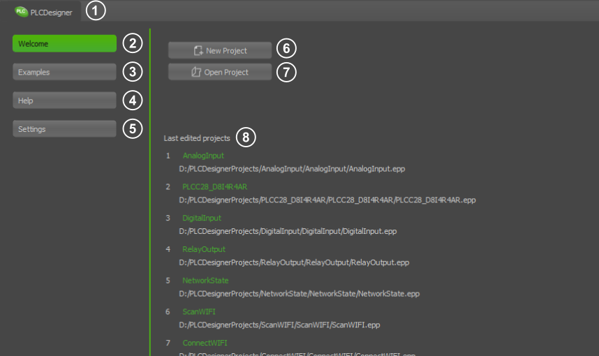
When you start PLCDesigner, the WelcomePage appears first. Here you can create new projects or open existing ones. You can also access the help file and sample projects.
|
- Switches between the Welcome Page and the Editor Window
- Shows the WelcomePage
- Example projects for the PLCDesigner
- Displays the help files for the PLC commands
- PLCDesigner settings
- Creates a new core or satellite project
- Opens a core or satellite project
- List of recently used projects
|
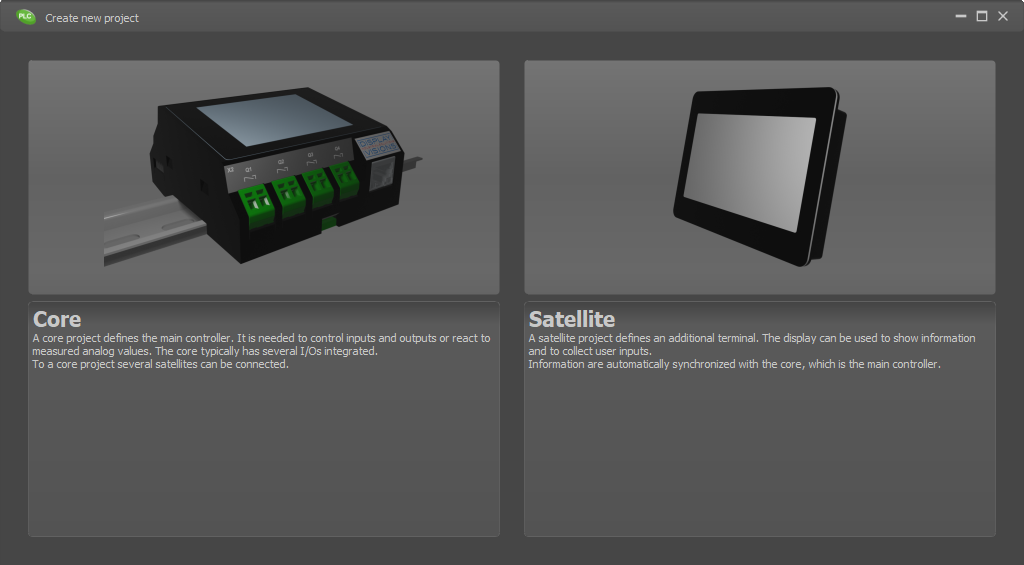
Create new project
When creating a new project, you must first select whether you want to create a core or satellite project.
The core is the master in the system. The communication of all participants runs through it. The satellite project is assigned to the core later in the PLCConfig editor.
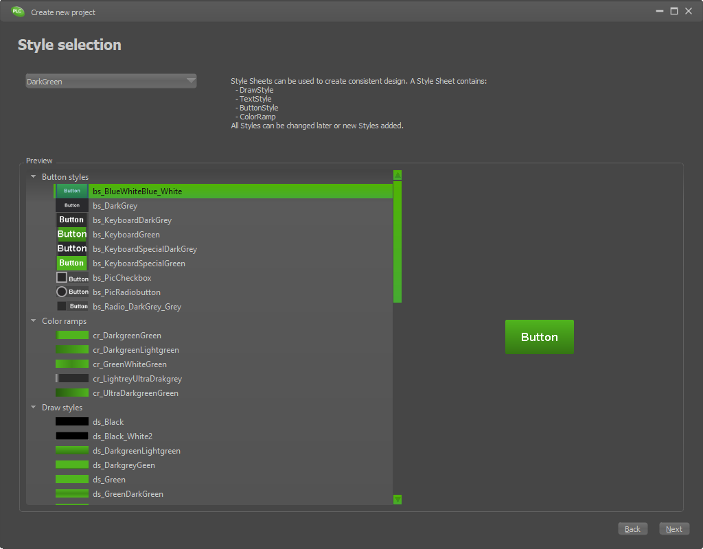
In a second step, you select a style template for the display. There is a default selection of styles. However, you can also create your own stylesheets, which can later be selected from the list. In addition, all styles can be changed and new ones created in each project.
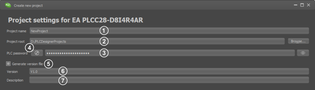
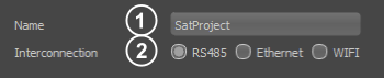
In the last step, you assign a project name and other settings for the project
|
- Project name
- Project directory
- PLC Password (used to login the satellite displays to the core)
Must be at least 6 characters long
Must have at least one of the special characters '&', '~', '#', '-', '_', '$', '%', '°'', '!', '?'
Must contain uppercase letter: A, B, C, ..., Z
Must contain lowercase letter: a, b, c, ..., z
Must contain arabic numerals: 0, 1, ..., 9
- Automatic password generation
- Activation of the version management
- Version name
- Version description
|
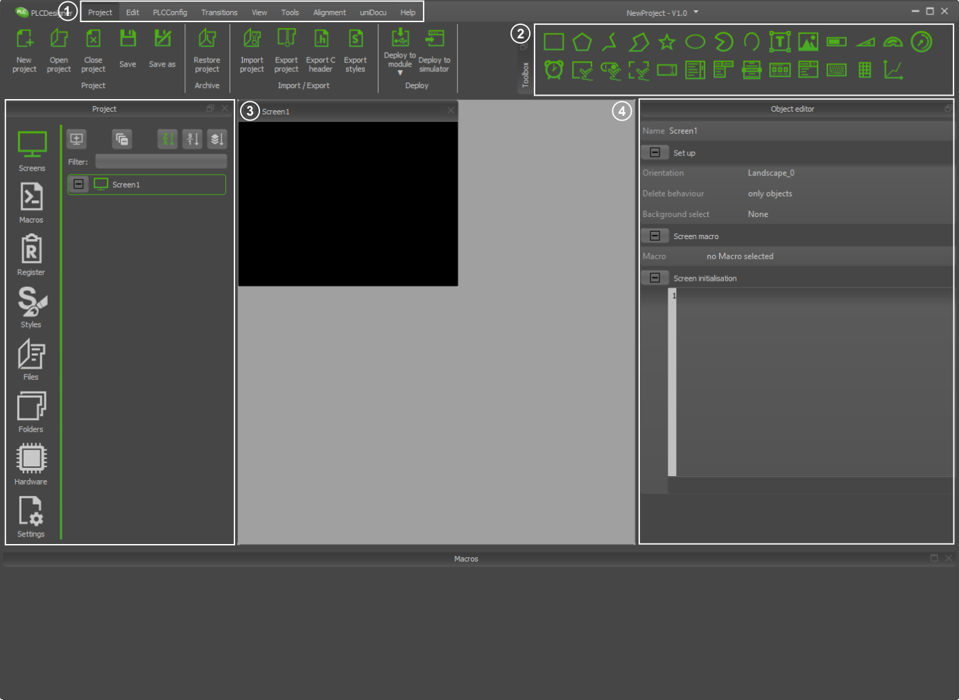
PLC Editor window
|
- Ribbon tab
- Toolbox
- Project elements
- Object editor
|
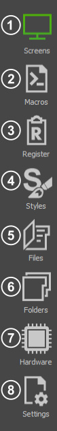
Project Elements
|
- Overview of all screens and their objects
- Creating and editing macros
- Creating and editing registers
- Create and change styles
- Embedded external files
- Embedded external folders
- Hardware settings
- Project settings
|
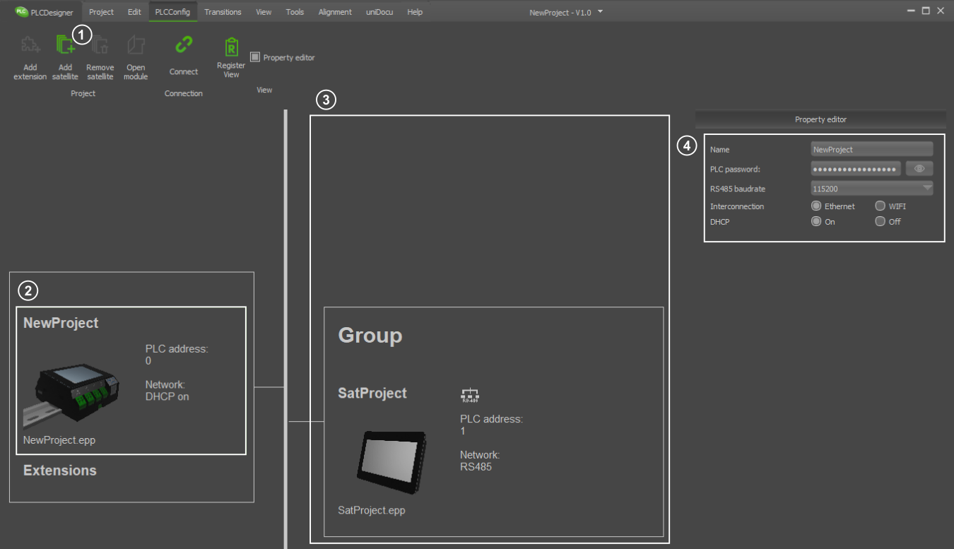
PLCConfig
|
- Add satellite
- Core module
- Satellite modules
- Network properties of selected module
|
Core settings
|
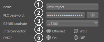
- Name: mDNS name of Core module
- PLC password:: The password (used to login the satellite displays to the core)
Must be at least 6 characters long
Must have at least one of the special characters '&', '~', '#', '-', '_', '$', '%', '°'', '!', '?'
Must contain uppercase letter: A, B, C, ..., Z
Must contain lowercase letter: a, b, c, ..., z
Must contain arabic numerals: 0, 1, ..., 9
- RS485 badrate:Set the baud rate for RS485 communication between the core and the satellite.
- Interconnection:Selects the desired connection channel between Core and Satellite. The RS485 connection is always active in the Core. A network connection is also always on. You can select between Ethernet and WIFI.
- DHCP:Specify whether you want to use DHCP
|
Satellite settings
|
- Name: mDNS name of satellite module
- Interconnection:: Selects the desired connection channel between Core and Satellite.You can choose between RS485, Ethernet and WIFI.
|
DHCP off settings
|
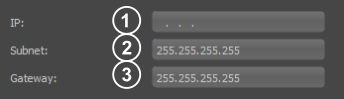
- Ip address: Ip address of the module
- Subnet:: Subnet of the module
- Gateway:Gateway of the module
|
WIFI settings
|
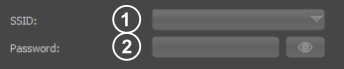
- SSID: WIFI SSID
- Password:: WIFI password
|
Register Settings
Under the menu item Register, registers, string registers and arrays can be created and edited. You can also select whether the individual registers should be synchronised with all connected modules.
Numerical and String registers
|
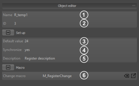
- Name: An individual name can be assigned to each register. The value can then be accessed directly with the register name (R_temp1).
- Id: A unique ID is assigned to each register. Many commands require this Id to address the correct register. In PLCDesigner you can also reach the Id with the beautified name ID{R_temp1}
- Default value numeric: Value the register has after power on. By default, the register is created as an integer register (signed 32Bit). If a floating point number is specified as default value, a float register (23 Bit Mantissa, 8 Bit Exponent, 1 Bit signed) is created.
Default value string: Value the register has after power on. Strings with a maximum of 200 characters are allowed.
- Synchronize register: If synchronisation is selected, the register value is automatically shared with all connected modules in the network.
- Description: A description can be added to each register.
- Change macro: The macro is called every time the register value changes.
|
Numerical and String defines
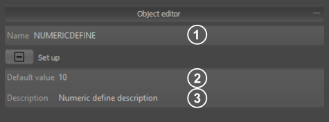
|
- Name: The name can be used to access the defines in the macros.
- Default value: Value of the numerical or string define.
- Description: A description can be added to each define.
|
Arrays and String arrays
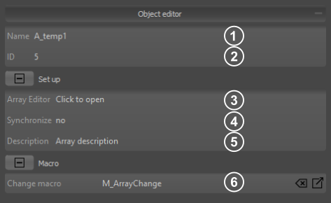
|
- Name: An individual name can be assigned to each array. The value can then be accessed directly with the array name and array index starting with 0 (A_temp1(0)).
- Id: A unique ID is assigned to each array. Many commands require this Id to address the correct array. In PLCDesigner you can also reach the Id with the beautified name ID{A_temp1}
- Array Editor: Opens the array Editor
- Synchronize array: If synchronisation is selected, the whole array is automatically shared with all connected modules in the network.
- Description: A description can be added to each array.
- Change macro: The macro is called every time a array value changes.
|
Array editor
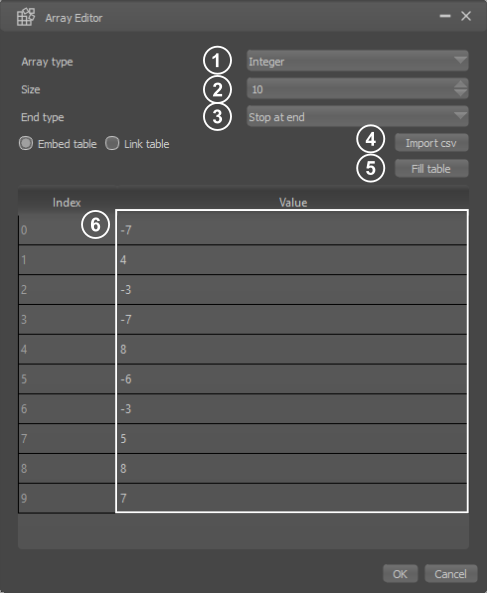
|
- Array type: Selection of the array typ (integer or float). This option is only available for numeric arrays.
- Size: Specifies the size (number of entries) of the array.
- Array end typ: This parameter defines whether the automatic filling of the array is aborted at the end or the write pointer automatically wraps around and overwrites the values again from the beginning.
- Import option: It is possible to fill the array with values from a CSV file. You can also choose whether the current values from the file should be entered permanently in the PLCDesigner or whether the file should be linked ( data changes in the file are then always automatically adopted in the PLCDesigner).
- Fill array: There are different possibilities to fill the default values of the array automatically (e.g. with zero, with random values).
- Default values: Values the array has after power on
|
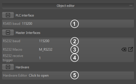
Hardware Settings
Under the menu item Hardware (available only for modules with hardware connections e.g. PLCC28) all settings regarding the connected hardware can be made.
|
- PLC RS485Baudrate: Set the baud rate for RS485 communication between the core and the satellite.
- Baudrate: Sets the baudrate of the master RS232 (Pin 1.19 RxD and 1.20 TxD). This setting is not available for all modules.
- RS232 Macro: The receive macro is called as soon as the specified number of bytes is stored in the receive buffer (see point 3). If more bytes are received until the macro is fully processed, the receive buffer can contain more bytes. This setting is not available for all modules.
- RS232 Receive trigger: Specifies the number of bytes after which the receive macro is called. A retrigger takes place after the reception macro has been completely processed. This setting is not available for all modules.
- Hardware Editor: Opens the Hardware Editor
|
Hardware Editor
After opening the editor, the used module is shown. If there is a mouse over event over the port pins, the name of the respective port pin is displayed. Settings can be made with a click. This is exemplified by the module EA PLCC028-D8I4R4AR. If additional extensions are connected, these are also displayed in the hardware editor.
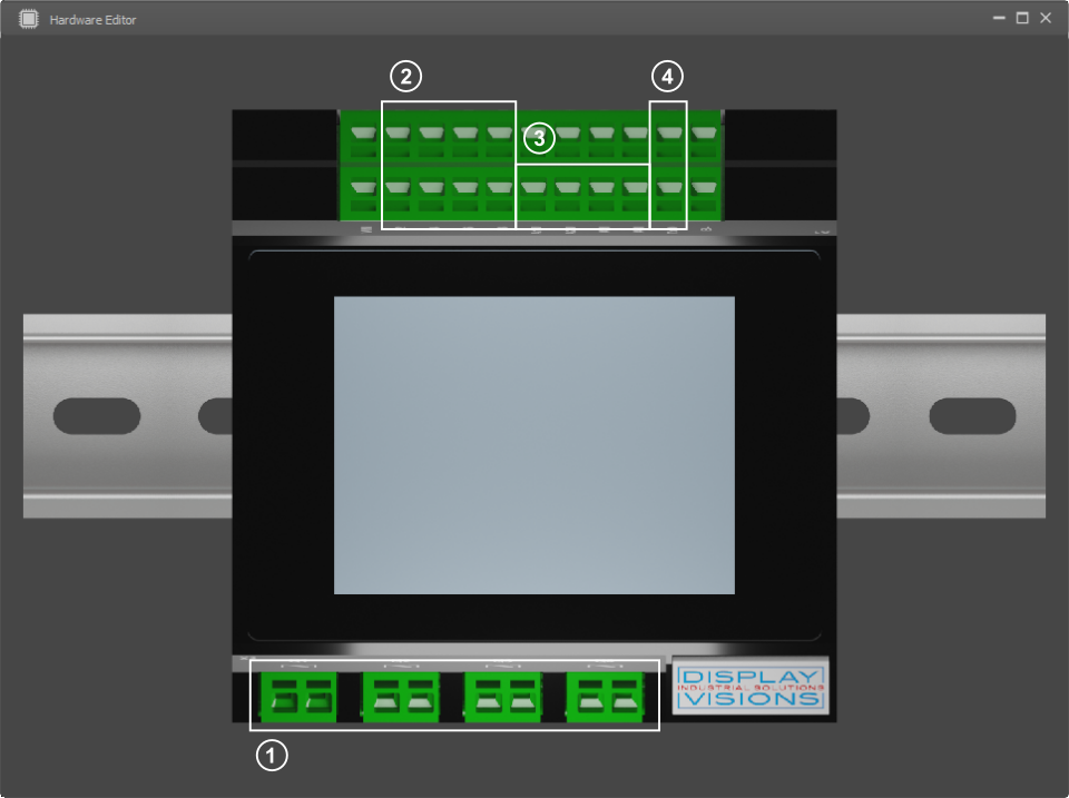
|
- Output pins
- Input pins
- Analog inputs
- RS232 Master interface
|
Hardware Output Settings
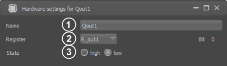
|
- Name of the output pin: An individual name can be assigned to each output. This name can be used to access the output in the macros. For example, to set the output with the name 'Qout1' to one, you have to use the command #HBW Qout1, 1.
- Assigned register:: A register can optionally be assigned to the outputs. The value of the Register changes automatically when the state of an output pin changes. If the register value is changed, the respective outputs change analogously. If you want to set the output of the selected port pin to one, as in the example above, you can also set bit 0 of register 'R_out1' to one
#VRI ID{R_out1}, (bitS(R_out1, Qout1Bit0)).
- Default state of the output pin after power on
|
Hardware Input Settings
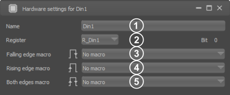
|
- Name of the input pin: An individual name can be assigned to each input. This name can be used to access the input in the macros. For example, if you want to read the state of the port pin with the name Din1, you must use the calculation
(bit(Din1))
- Assigned register:: A register can optionally be assigned to the inputs. Each time an input pin is changed, the register is automatically updated. If you want to read the status of the output with the name 'Din1', you can alternatively read bit 0 of register 'R_Din1':
(bitT(R_Din1,Din1Bit0))
- Falling edge macro: The macro is called on each falling edge of the port pin.
- Rising edge macro: The macro is called on each rising edge of the port pin.
- Both edges macro: The macro is called on each edge of the port pin.
|
Hardware Analog Settings
|
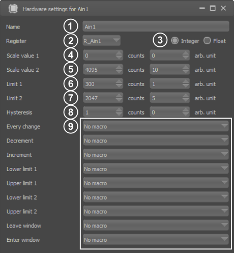
- Name of the analog input pin: An individual name can be assigned to each analog input. This name can be used to access the analog input in the macros. To read in the current analog value, use the calculation (analog(Ain1)). The calculation returns a value between 0 and 4095. You can scale the value in the settings (see points 4 and 5). The calculation (analog(Ain1,1)) returns the user-defined value.
- Assigned register: A register can optionally be assigned to the analog input. Each time the analog value changes (under consideration of the hysteresis see point 8), the register is automatically updated. The value can then be accessed directly with the register (R_Ain1). The register always contains the user-defined value of the analog channel.
- Register type: Selection of the register typ (integer or float).
- Scale value 1: The analog channel returns a value between 0 and 4095. The value range of the output can be adjusted individually with the settings scale value 1 and scale value 2.
- Scale value 2: The analog channel returns a value between 0 and 4095. The value range of the output can be adjusted individually with the settings scale value 1 and scale value 2.
- Limit 1: Two limits can be assigned to each analog channel. There are different macros that are called depending on the value and the limits.
- Limit 2: Two limits can be assigned to each analog channel. There are different macros that are called depending on the value and the limits.
- Hysteresis: Specifies after which change of the analog channel the register value is changed and the affected macros are called.
- Analog macros: Various macros can be assigned to each analog channel, which are called depending on the value and the set limits.
|
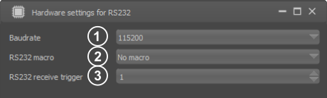
Hardware RS232 Settings
|
- Baudrate: Sets the baudrate of the master RS232
- RS232 Macro: The receive macro is called as soon as the specified number of bytes is stored in the receive buffer (see point 3). If more bytes are received until the macro is fully processed, the receive buffer can contain more bytes.
- Receive trigger: Specifies the number of bytes after which the receive macro is called. A retrigger takes place after the reception macro has been completely processed.
|
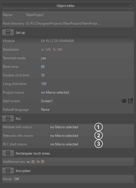
Project Settings
|
- Module info macro: The macro is started when changes occured regarding the connected modules.
- Network info macro: The macro is started when changes occured regarding the network connection of the module.
- PLC start macro: The macro is started when PLC has bootet completly.
|